
OBJECTIVE
To develop, design and simulate an IC Engine Piston Assembly using multi-body dynamics in Solidworks to learn all the characteristics and processes associated with it.
THEORY
- Piston motion analysis is the study of the reciprocating motion of the piston in the cylinder and the motion of the assembly attached i.e. piston, connecting rod, end cap, crankshaft & wrist pin/Godgeon pin.
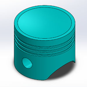
- Piston head is a component of reciprocating engines, reciprocating pumps, gas compressors and pneumatic cylinders, among other similar mechanisms. It is the moving component that is contained by a cylinder and is made gas-tight by piston rings. In an engine, its purpose is to transfer force from expanding gas in the cylinder to the crankshaft via a piston rod and/or connecting rod.
- Connecting rod is the component connecting between the godgeon pin and the crank held with end cap at one of its end opposite to the godgeon pin.
- End Cap is connected to the end of the connecting rod, which is assembled together to the crank.
- Crank is the mechanical part that converts reciprocating motion from the piston into rotational motion.
- Godgeon Pin (Wrist pin) is the pain that holds the piston and connecting rod together.
CAD MODELS


MOTION ANALYSIS
This project aims to analyze the motion analysis of the piston and the parameters set to achieve the plots of linear displacement are given below
PROCEDURE
Enable to view the temporary axis
Apply motor to the axis at the circular part of the crank from outside with following parameters:
- RPM:2000
- Clockwise direction
Apply contact to the bodies a the following:
- Crank and End cap
- Crank and Connecting rod
- Connecting rod and Godgeon pin
- Godgeon pin and Piston head
Apply gravity in Y-Direction
Go to settings, update the following parameters:
- Turn on Precise-contact
- FPS:7200
Run the Simulation and wait for the analysis. It will take a long time since the process is involved with FPS of 7200 and 2000RPM
Once done, Go to PLOT and select the following parameters:
- Select, Force/Velocity/Acceleration Tab
- Select, Linear Displacement
- Select, Magnitude
- Click, OK
Plot will be seen now. Then, from the feature tree, right click on results and update the following
- Rename the plot
- Export the data to excel
Next, run the simulation and save the animation file.
Save the files with motion analysis, assembly and part files.
SIMULATION
Crank and Wrist pin are in same plane/line
Plot for linear displacement

CONCLUSION
- From the plots obtained, we can see that Linear Displacement increases as we move from negative wrist pin offset to positive wrist pin offset
- Therefore, the magnitude of the linear displacement increases with change in offset entities.
- Also from the graph obtained after superimposing, we can see that for a given time frequency of rotation of piston with respect to wrist pin, offset negative is higher comparatively to one with zero offset and pin with zero offset has higher frequency than one with a positive offset.


